

The blueprints sitting on your desk represent more than a technical requirement; they are the definitive script for your future home’s story. It is completely natural to feel a sense of unease when staring at a dense grid of annotations and 2D sections. You likely worry that a missed detail today will become a costly structural flaw tomorrow. Learning how to read architectural drawings for a house is the vital bridge between your vision and the finished build. It transforms a flat piece of paper into a 3D sanctuary you can truly understand.
This masterclass will empower you to decode the complex language of your plans so you can walk through your rooms in your mind long before the foundation is poured. We believe that an informed homeowner is a confident partner in the design process. You will learn to identify essential symbols, recognize potential layout issues early, and communicate with your builder with absolute clarity. Through an uncompromising focus on detail, we provide the tools you need to ensure your investment is protected and your design is realized with precision. From understanding the 2024 International Residential Code nuances to mastering scale, this guide prepares you for a successful project.
Key Takeaways
- Identify the title block as the essential project anchor to ensure you are always reviewing the most recent and authoritative revisions.
- Master the visual shorthand of line weights and symbols to understand how to read architectural drawings for a house with the confidence of a seasoned professional.
- Distinguish between floor plans, elevations, and sections to visualize both the interior flow and the distinguished exterior character of your home.
- Conduct a strategic review of circulation paths and functional zones to ensure your layout supports a sophisticated and effortless lifestyle.
- Leverage the design-build advantage to bridge the gap between complex architectural concepts and the flawless execution of your custom project.
The Foundation of the Blueprint: Starting with the Title Block
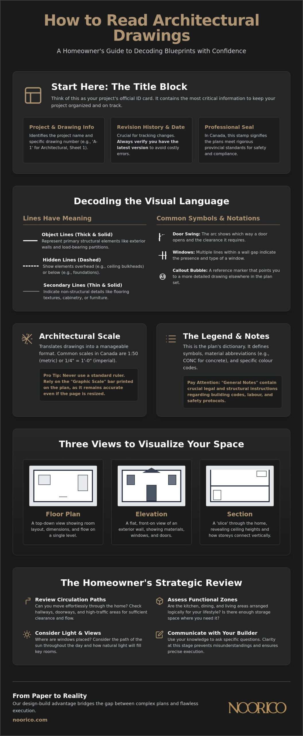
The title block is the definitive “ID card” of every architectural drawing. It serves as the essential organizational anchor for your entire project. While it might appear as a mere administrative border, it contains the vital data required to maintain order during a sophisticated build. Within this structured space, you will find the project name, the specific drawing number, and the revision history. Understanding how to read architectural drawings for a house begins with these details. They ensure you are always reviewing the most current version of the vision. The drawing number often follows a logical sequence, such as “A” for architectural or “S” for structural, allowing you to navigate the set with quiet confidence.
The “Date of Issue” is particularly critical. It serves as the single source of truth for your project managers and builders. In a high-end renovation or custom build, multiple versions of a plan may exist. Relying on an outdated sheet can lead to significant errors in execution. In Canada, look for the professional seal of the architect or firm. This stamp signifies that the plans meet rigorous provincial standards and have undergone an uncompromising review for safety and compliance. It is the mark of a seasoned professional who stands behind the integrity and longevity of the work. Our project managers meticulously verify every revision date in the title block to prevent construction delays, ensuring your project remains on schedule and your investment is protected.
Understanding Architectural Scales
An architectural scale translates vast, aspirational structures into a manageable, readable format. Common scales used in Canada include the metric 1:50 or the imperial 1/4″ = 1′-0″. Precision is paramount here. You should never attempt to measure a drawing with a standard ruler. Paper can shrink or stretch over time; digital files can be unintentionally resized during viewing. Instead, rely on the “Graphic Scale” provided in the title block or margins. This visual bar grows or shrinks with the drawing itself, ensuring your measurements remain precise regardless of how the plan is displayed or printed.
The Legend and General Notes
The legend acts as the essential translator for the document’s complex visual shorthand. It defines specific symbols, fixture locations, and material abbreviations, such as WD for wood, CONC for concrete, or even specific colour codes for exterior finishes. Mastering the legend is a fundamental step in learning how to read architectural drawings for a house, as it clarifies the architect’s intent without ambiguity. Beyond these markers, “General Notes” often hold the most significant structural and legal warnings. These notes outline specific labour requirements, local building code adherence, and safety protocols. They are not merely suggestions. They are high-value instructions that protect your financial investment and ensure your design is realized with absolute precision.
Decoding the Visual Language: Symbols, Lines, and Notations
The visual language of a blueprint is a sophisticated shorthand that prioritizes precision over aesthetics. Every line has a specific weight and purpose. Heavy, bold lines traditionally represent primary structural elements like exterior walls or load-bearing partitions. In contrast, lighter lines denote secondary details such as flooring textures, cabinetry, or furniture. Mastering how to read architectural drawings for a house involves recognizing this hierarchy immediately. Visible “Object Lines” show what is physically present in the space, while dashed “Hidden Lines” reveal elements that are overhead, such as a bulkhead, or buried, such as a foundation footing.
Professional organizations like Architects Creating Homes provide rigorous standards for reading architect’s documents, ensuring that every symbol is universally understood by tradespeople. For example, a door is never just a gap; it is an arc that indicates the direction of the swing and the clearance required. This arc is essential for planning furniture placement and ensuring a natural flow through the home. Similarly, callout symbols act as navigational anchors. These bubbles or arrows contain numbers that point you to a specific page or detail elsewhere in the set, allowing you to zoom in on complex intersections of the design with absolute clarity.
The Anatomy of a Wall
Distinguishing between load-bearing and non-load-bearing walls is vital for any major renovation. Load-bearing walls are often indicated by specific hatching or a thicker profile to signify their structural importance. Canadian drawings also feature specific symbols for insulation, often shown as a zigzag batt pattern, and vapour barriers, represented by a thin, continuous line. These layers are critical for our climate, and recognizing their thickness in the plan helps you understand the true net square footage of your rooms. Our team specializes in architectural design that balances these technical requirements with aspirational aesthetics.
Electrical and Plumbing Notations
Electrical notations identify the precise placement of outlets, light switches, and ceiling fixtures. Plumbing stacks are typically shown as small circles within wall cavities, indicating the vertical paths for water and waste. The Reflected Ceiling Plan (RCP) is a sophisticated tool for modern lighting design. It acts as a mirror image of the floor to show how fixtures, coffers, and skylights interact with the architectural volume. By reviewing the RCP alongside the floor plan, you can ensure that your lighting layout is both functional and elegant, avoiding awkward shadows or poorly placed switches before construction begins.
Visualizing the Space: Navigating Plans, Elevations, and Sections
Moving beyond individual symbols requires an understanding of how different perspectives combine to form a complete architectural narrative. A full set of plans is not a repetitive collection of drawings; it is a synchronized system of views that describes every dimension of your future home. Mastering how to read architectural drawings for a house allows you to synthesize these various viewpoints into a singular, cohesive vision. While the floor plan provides the essential horizontal layout, the elevations and sections provide the vertical context and structural depth necessary for a high-end build.
Each drawing type serves a distinct purpose in the design process. The floor plan is a bird’s-eye view, sliced horizontally about four feet above the floor to reveal the flow between rooms and the placement of structural partitions. Elevations act as the “face” of the home, showing the exterior heights, material transitions, and the sophisticated interplay of stone, wood, or glass. Sections provide a vertical slice through the building, revealing the internal skeleton, floor thicknesses, and the precise height of each ceiling. Finally, detail drawings act as a magnifying glass, focusing on complex intersections like window sills or custom stair railings to ensure every element is executed with uncompromising quality.
Constructing a Mental Walkthrough
You can use the floor plan to perform a mental walkthrough of your home long before the foundation is poured. Start at the front door and trace your path through the foyer, paying close attention to sightlines. A well-designed custom home prioritizes these visual axes to create a sense of grandeur and openness. By cross-referencing the floor plan with the exterior elevations, you can visualize how natural light will penetrate specific rooms at different times of the day. In high-end design, the sections are particularly vital. They allow you to evaluate ceiling heights, ensuring that primary living spaces possess the airy, voluminous feel that defines modern luxury.
Coordinating Between Views
Effective project management relies on the ability to move seamlessly between different sheets in the set. Look for “Section Marks” on your floor plan; these are typically circles with an arrow indicating the direction of the cut and a number identifying the corresponding drawing. It is essential to verify that the window positions shown on your elevations align perfectly with the openings on your floor plans. For interior spaces, such as professional-grade kitchens, interior elevations define the precise height of cabinetry and the placement of intricate millwork. We utilize this multi-disciplinary approach to ensure that what is visualized on paper is realized with absolute precision in your finished home.
The Homeowner’s Strategic Review: What to Look for Beyond the Lines
Understanding how to read architectural drawings for a house is merely the starting point for a successful build. The true value lies in your ability to perform a strategic review that prioritizes your lifestyle over the abstract lines on the page. Begin by scrutinizing the circulation paths within the floor plan. While a standard hallway might meet the minimum building code, a width of five feet or more creates the sophisticated, gallery-like atmosphere expected in a custom home. Similarly, evaluate the kitchen triangle. Ensure the distance between the sink, range, and refrigerator is optimized for a professional-grade culinary experience, avoiding unnecessary steps or congested pathways during meal preparation.
Identifying these nuances is a critical part of how to read architectural drawings for a house effectively. Look for subtle “clashes” that can disrupt daily life before they are set in stone. Check if light switches are positioned behind door swings or if plumbing stacks for upper-floor bathrooms are located directly adjacent to quiet primary bedrooms. Fenestration, or the arrangement of windows, requires a balanced assessment. Your drawings should maximize panoramic views and natural light while strategically shielding private areas from neighbouring properties. This level of scrutiny ensures that your home is as functional as it is beautiful.
Furniture and Spatial Planning
Ask your designer to “ghost in” standard furniture pieces on the floor plans to test the true scale of each room. This practice reveals whether there is sufficient wall space for your art collections or large-scale televisions. Verifying that door swings don’t interfere with intended furniture placement prevents frustrating layout limitations during the move-in phase. Our interior design services integrate these practical considerations with high-end aesthetics to create a seamless living environment.
Future-Proofing Your Design
A visionary project anticipates the future needs of its inhabitants. Ensure your plans include rough-ins for emerging technology or potential home additions gta. Evaluate the adaptability of secondary rooms for aging-in-place or evolving home office requirements. Finally, confirm that mechanical rooms are sized appropriately for high-efficiency HVAC systems. This allows for future upgrades without compromising the structural integrity of your home, ensuring your investment remains relevant for decades.
From Paper to Reality: The NOORICO Design-Build Advantage
The transition from a conceptual blueprint to a physical structure requires more than technical skill. It demands a seamless integration of vision and execution. While mastering how to read architectural drawings for a house empowers you as a homeowner, the success of the build hinges on the synergy between the architect and the construction team. Our design-build model eliminates the traditional friction often found in residential projects. Instead of disparate entities working in silos, our designers and builders collaborate from the very first sketch. This unified approach ensures that every detail you have carefully reviewed on paper is precisely what is manifest in your finished home.
Our project managers serve as the vital link in this process. They translate complex architectural notations into actionable site instructions with quiet confidence. They possess the practical grit required to oversee a high-intensity site while maintaining the sophisticated elegance of the original design. This persistent dedication to the final product means that technical challenges are solved before they ever impact the construction schedule. By maintaining total accountability for both the design and the build, we provide a trust-based experience that safeguards your significant investment and ensures a superior result that stands the test of time.
A Visionary Partnership
We don’t view ourselves as a mere service provider. We act as your multi-disciplinary guide through the intricate intersections of architectural design, finance, and execution. With decades of industry experience, we understand the nuances of high-end residential transformations in a way that few can match. Our role is to navigate the complexities of building codes and structural requirements so you can focus on the creative achievements of your new space. We bridge the gap between aspirational design and the grounded reality of construction, providing a steady hand throughout the entire journey.
Your Next Step in the Design Journey
Learning how to read architectural drawings for a house is the first step toward a successful custom project. To supplement your understanding of 2D plans, we utilize advanced visualization techniques that bring your future home to life in three dimensions. An initial consultation allows us to align your unique vision with our professional expertise and regional knowledge. This collaborative start ensures that every line on the blueprint serves your long-term goals and aesthetic preferences. Contact NOORICO today to begin your sophisticated home building experience and transform your vision into an enduring architectural legacy.
Realizing Your Vision Through Architectural Clarity
Mastering how to read architectural drawings for a house is the definitive step in transforming a conceptual design into a tangible sanctuary. You’ve learned to decode the title block, interpret complex symbols, and synthesize multiple views to build a precise mental model of your future home. This knowledge empowers you to conduct a strategic review that prioritizes flow, functionality, and future adaptability. By understanding the vertical context of sections and the face of elevations, you move from being a spectator to a confident participant in the design process.
At NOORICO, we bring over 25 years of established expertise to every luxury residential project. Our integrated design-build project management ensures that your sophisticated vision is realized with uncompromising quality and persistent dedication. We act as your visionary partner, navigating the intersection of architectural design and execution to protect your investment. Your journey from paper to reality deserves a guide who values precision as much as you do. Partner with NOORICO for Your Custom Build today and begin the transformation of your aspirational lifestyle into an enduring architectural legacy.
Frequently Asked Questions
What is the difference between an architectural drawing and a blueprint?
Architectural drawings are the modern standard for technical design; “blueprint” refers to an obsolete 19th-century chemical printing process that produced white lines on blue paper. Today, we utilize high-resolution digital plots and data-rich models to ensure absolute precision. Understanding how to read architectural drawings for a house involves recognizing these documents as the definitive legal and structural script for your project.
How do I know if the dimensions on the plan are for the inside or outside of the wall?
Dimensioning conventions typically measure exterior walls to the outside face of the structural sheathing or framing. Interior partitions are frequently measured to the centre of the wall studs or the finished face of the drywall. You should always verify the specific dimensioning standards by reviewing the “General Notes” or the legend on the first few pages of your plan set.
What does “N.T.S.” mean on an architectural drawing?
“N.T.S.” stands for “Not to Scale.” This notation serves as a critical warning that the specific drawing or detail should not be measured with a physical ruler or scale. It’s often used when a drawing has been adjusted to fit a specific sheet size or when the focus is on the assembly of materials rather than their absolute dimensions.
Can I make changes to the architectural drawings once construction has started?
You can implement changes after construction begins, but these modifications require a formal Change Order. Making adjustments during the build phase often incurs additional costs and can significantly disrupt the established construction schedule. It’s best to finalize your design vision during the planning stage to ensure the project’s financial and organizational stability remain intact.
How many sets of drawings are typically included in a custom home design package?
A comprehensive custom home package typically contains between 15 and 30 sheets, depending on the project’s complexity. This set includes the site plan, floor plans for every level, exterior elevations, building sections, and intricate detail drawings. Larger projects often require separate structural, mechanical, and electrical sets to provide every trade with a precise and dedicated roadmap.
What is a site plan and why is it separate from the floor plans?
A site plan provides a bird’s-eye view of your entire property, showing the home’s position relative to property lines, setbacks, and existing trees. It’s separate from floor plans because it focuses on exterior logistics such as grading, drainage, and utility connections. This document is essential for obtaining municipal permits and ensuring your home is perfectly situated on its unique landscape.
How do architects show different floor levels on the same sheet?
Architects use distinct titles and clear labels to differentiate floor levels when they appear on the same sheet. If a single floor plan is too large for the page, a “match line” is used to show where the drawing continues on a subsequent sheet. Each level is clearly identified in the title block to ensure there’s no ambiguity for the project managers or tradespeople.
Why are there so many different types of lines on a single drawing?
Different line types and weights create a visual hierarchy that makes a complex technical drawing readable. Solid heavy lines represent primary structural walls, while dashed lines might indicate overhead bulkheads, hidden foundation footings, or property boundaries. Mastering these line types is a fundamental part of how to read architectural drawings for a house, as it allows you to distinguish between visible and hidden elements.